Functional Safety

Industrial & Automotive Functional Safety: ISO 26262 & IEC 61508

Functional safety for safety-critical systems: IEC 61508 as the cross-industry parent standard for E/E/PE systems, ISO 26262 as its automotive derivation with ASIL classification. We accompany ASIL-D and SIL-3 programmes from hazard analysis to the safety case, with itemis CREATE for modelling and itemis ANALYZE for comprehensive traceability.

Fundamentals

Functional Safety: The Bridge Between Standard and Practice

Functional safety is non-negotiable. The path to achieving it, however, must be worked out anew in every project, in the tension between the strict demands of safety standards and the established architectures and processes of an existing product.

itemis has been accompanying this translation work across industries for many years. Wherever a system failure can endanger people, we bring structure to compliance:

  • Automotive: ISO 26262
  • Medical technology: IEC 62304, IEC 60601 & ISO 80601
  • Railway: EN 50716 & EN 50129
  • Agricultural machinery: ISO 25119
  • Machinery: IEC 62061
  • Aerospace: DO-178C

The common root: All these sector standards are based on IEC 61508. Those who know only a single derivation often mistake its peculiarities for universal laws. Through our cross-industry practice, we understand the deeper intentions behind the requirements. We apply this knowledge purposefully to optimise processes, rather than blindly following standards.

We don’t just advise: we enable (Enabler approach)

Our role is never that of a pure assessor who delivers a verdict at the end of a project and leaves. itemis sees itself as an enabler: We empower development teams to live safety not as an afterthought for documentation, but as an integral, value-adding part of their Systems Engineering.

This page shares exactly this practical knowledge. It is part of our cross-functional knowledge platform for holistic compliance, examines functional safety in detail, and shows where semi-automated processes can already responsibly support engineers today.

Quo vadis

Quo vadis, Functional Safety Engineering?

The Evolution Towards the “Living HARA”

The future belongs to the “Living HARA”. The hazard analysis and risk assessment must no longer be a static document. It must be treated as a continuously maintained work product, directly linked to the system model and responding dynamically to changes.

This becomes all the more important as development cycles shorten: where development is iterative and systems receive updates even after release (over-the-air), the safety assessment must continuously keep pace with every cycle, rather than being produced just once at a milestone.

The document loses its role as the single “source of truth”. It becomes instead an automatically generated view of a central model in which the actual information resides. This only works, however, if the safety artefacts are model-based and their dependencies are machine-readable. The same naturally applies to the FMEA and the FTA.

Traceability: The Digital Backbone of Safety

The backbone of this linkage is comprehensive traceability. Only a continuous derivation chain from the top-level safety goal through refined safety requirements all the way to implementation and test case makes changes manageable at all:

  • When hazards change: If a hazardous event is re-assessed, the trace links immediately show which requirements, architecture elements, analyses and test cases are affected, and which remain untouched.
  • Within the analyses: If an architecture element changes, the associated FMEA entries must be re-assessed. Since Failure Modes from the FMEA feed into the fault tree as Basic Events, every change propagates directly through to the FTA.

The scalability factor: Those who do not maintain these cross-references as digital trace links must laboriously reconstruct them by hand with every change. At short cycles, this does not scale: an impact analysis that costs weeks of manual work does not fit into any sprint. Without these chains, “living” merely means that a document is frequently edited, and gaps emerge in the safety evidence that only the assessor will find, when it is too late. With them, every change becomes an answerable question rather than a re-assessment from scratch.

What the Standards and Quality Models Require

The standards have long anticipated this step. Traceability between requirements, implementation and verification is required by all sector standards in one form or another: ISO 26262, IEC 62304, EN 50716 and DO-178C, which even lists trace data as a standalone work product.

And not just them: process quality models also require bidirectional traceability as a baseline practice: ISO/IEC 330xx (the standardised assessment family), Automotive SPICE (ASPICE) (as its specific industry derivation), CMMI.

The conclusion: Those who want to demonstrate process maturity cannot avoid digital traceability (just as those who want to demonstrate functional safety cannot), and this must be continuous.

How comprehensive traceability is built in practice (from tool integration to the Traceability Information Model) is covered on our Requirements Traceability page.

MBSE

The End of the Static Document: Why the Burden of Proof Has Shifted

The document-centric safety approach is a relic of a bygone era. It dates from a time when systems remained largely stable across their development cycle and all subsequent lifecycle phases: HARA, safety concept and safety case were produced as pure text documents, frozen at milestones and regarded thereafter as the binding status.

A holistic system development across the entire lifecycle (as per ISO 15288) no longer adheres to this rigid rhythm.

The Risk: Late Changes to the System Boundary

A frozen document becomes obsolete the moment the system boundary changes. And this happens regularly and late in practice:

  • The scenario: Late changes to the system boundary frequently force a complete re-assessment of Hazardous Events, often just a few weeks before the final Design Freeze.
  • The consequence: Those who maintain their hazard analysis as a static document are inevitably working against copies. Consistency can no longer be guaranteed, and the project finds itself in acute need of explanation before the assessor.

A Look at the Standards: Semi-Formal Methods Have Long Been Mandatory

This trend is not new: it was already apparent in the requirements of the standards years ago. None of them prescribe a specific tool or a concrete modelling language, but a look at the method tables speaks a clear language:

StandardSafety levelRecommendation for (semi-)formal methods / modelling
ISO 26262-8 & -6From ASIL CHighly recommended (for specification & SW architecture design)
IEC 61508-3From SIL 3Highly recommended (formal methods for highest levels)
EN 50716Higher SIL levelsHighly recommended (modelling as its own technique group)

Aviation has already codified model-based development and verification with DO-331 since 2011 as a project-applicable supplement to DO-178C.

The Reversal of the Burden of Proof

Those who work purely in natural language and document-based approaches at high criticality levels have long been deviating from the strong recommendations of the standards. In an audit, this leads to a turning point:

The burden of proof has long since been reversed: Those who forego model-based approaches must explicitly justify this deviation to the assessor. It is not model-based development that requires justification: it is its absence.

Model-Based Systems Engineering (MBSE) is therefore no longer a matter of style. It is the indispensable prerequisite for safety analyses to keep pace with the enormous rate of change in modern system development at all.

Safety & Security

Safety & Security: Two Perspectives on the Same System Context

The present and future of functional safety does not exist in a vacuum. Every safety analysis must begin with the definition of the subject under consideration: which system is being assessed, where are its boundaries, and which interfaces are included?

Although the various sector standards use different terms and set their own emphases here, the core question is identical everywhere: What belongs to the system, and what does not?

System Boundaries Across Industries

Industry / StandardTerm for the boundaryFocus
Automotive (ISO 26262)Item definitionDelineation of a function at vehicle level.
Medical technology (IEC 62304)Intended purposePurpose of the medical device and patient safety at the centre.
Machinery (ISO 12100 / IEC 62061)Machine boundarySpatial, temporal and functional limits of the installation.

Those who draw this system boundary too narrowly unconsciously shift safety-relevant interfaces out of their own area of responsibility, and painfully discover during the assessment that no one has taken care of them.

The Major Overlap with Cybersecurity

It is exactly at this system boundary that functional safety overlaps massively with cybersecurity (e.g. according to ISO/SAE 21434 and IEC 62443):

  • The same subject, two perspectives: Hazard analysis (HARA) and threat analysis (TARA) examine exactly the same system. Safety protects the environment from the system: both from unintended malfunctions and unforeseen inadequacies. Security protects the system from the environment: specifically from deliberate, malicious attacks.
  • Interactions upon changes: Every change to the system or its environment, but also every newly discovered vulnerability, potentially affects both disciplines. A security patch can alter the timing behaviour of the software and thereby endanger safety; a new safety function can open new attack vectors.

Practical conclusion: Safety engineering that ignores these interactions and works in silos is planning against reality. Only an integrated approach, based on a shared, model-based system architecture, ensures that safety and security go hand in hand.

Tool Qualification

Tools for Functional Safety Engineering: Reframing the “Make or Buy?” Question

The more tools and automation enter the safety lifecycle, the more frequently an ostensibly uncomfortable question arises: that of tool qualification (e.g. according to ISO 26262-8, Chapter 11).

The practical answer, however, is “always qualify” less often than many companies assume.

The Qualification Compass: When Is a Tool Investment Necessary?

Whether a tool must be qualified is not decided categorically, but along a precise risk and trust assessment:

  • Error introduction (Tool Error): Can a defect in the tool itself introduce a critical safety error into the product or software?
  • Error detection (Tool Detection): Can the tool prevent an already existing safety error from being detected in the process?
  • Process-level assurance: Assurance of the process around the tool is often sufficient, for example through redundant checks or reviews in subsequent development steps.

The New Make-or-Buy Assessment

As automation in the safety lifecycle increases, tool qualification shifts from a rare but tedious compliance obligation to a recurring, strategic engineering decision:

StrategyWhen appropriate?The economic leverage
Buy (Qualified product)For standard tasks and deeply integrated development tools (e.g. compilers, modelling tools).The manufacturer supplies the qualification kit. This saves immense internal validation effort.
Make (Qualify own tool)For highly specific, proprietary in-house scripts or tailored toolchains that generate genuine USP.Qualifying your own tool safeguards the team’s tailored, highly efficient workflow.

Our approach as an enabler: We help you not only to select or develop the appropriate tools, but also to jointly assess the actual risk. The goal is always: As much automation as possible with as little qualification effort as necessary.

Partial Automation

Partial Automation: Where It Is Already Revolutionising Day-to-Day Engineering

Where does automation in safety lifecycle engineering already deliver genuine, measurable benefit today? Two concrete practical examples show the way:

1. Automated Dependent Failure Analysis (DFA)

A prime example is the Dependent Failure Analysis. Those performing an ASIL decomposition (for example, splitting an ASIL-B target into two times ASIL A(B)) must demonstrate the strict independence of the decomposed elements. In practice, this proof (for example, for the independence of power supplies or memory areas) is one of the most demanding tasks of all.

Here, engineering knowledge can be brought into a machine-verifiable form in conjunction with modern AI:

  • The ontology as a rule set: The underlying independence rules of the standards are defined as an unambiguous ontology.
  • Continuous checking: The system model is checked automatically and continuously against the rules. Violations become immediately apparent when they arise, not months later in a review.
  • LLM support as an accelerator: We use suggestions generated by Large Language Models (LLMs) to map the expert knowledge encoded in the ontology precisely to the domain- and customer-specific entities in the system.

The effect: This does not replace full formal verification, but it drastically reduces the manual review effort. This pattern (formalising expert knowledge as verifiable rules and running them continuously against the central model) is naturally transferable to further safety requirements.

2. Semi-Automatically Generated Redundancy in the Toolchain

A further powerful principle breaks with an old dogma: redundancy was previously an extremely expensive means of error prevention in the final product. Through partial automation, it becomes an affordable, highly efficient means of error detection in the development process.

The principle in vertical systems and software engineering:

  1. Independent toolchains: Two mutually independent, semi-automated toolchains (regardless of whether these work in a partially agentised, i.e. AI-supported, manner or in a classically rule-based way) derive the same engineering artefacts.
  2. The comparison: If contradictory results arise during subsequent testing, this discrepancy becomes an extremely valuable signal.
  3. Error detection: Errors in the toolchains or misunderstandings in the specifications become immediately visible.

With this approach, development teams gain double assurance without double the manual effort.

Agentic Engineering

Agentic Safety Engineering: Not for the Core, but a Major Lever for the Grey Zone

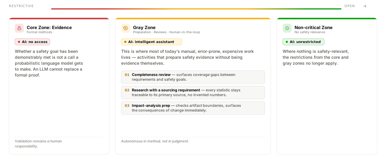
What role do AI agents (Agentic AI) play in functional safety? Our answer is nuanced and based on a clear division of the safety lifecycle into three zones:

Three-zone model: core zone with evidence (AI: no access), gray zone with preparation and reviews (AI: intelligent assistant), non-critical zone (AI: unrestricted)

It is precisely in this grey zone (activities that prepare, support or accelerate safety work, but whose results are not themselves evidence) that the largest share of manual, error-prone and costly work is found today.

  • In the core area (evidence), probabilistically operating language models have no place as an autonomous instrument. An LLM cannot replace formal proof.
  • In the grey zone, AI agents as intelligent assistants with Human-in-the-Loop already deliver enormous value. The human remains responsible; the agent extends their field of view.

Three Concrete Use Cases for AI Agents in the Grey Zone

1. Intelligent Review Support for Completeness

One of the most insidious gaps in the safety case arises when all requirements are fulfilled, but proof is missing that they adequately cover the higher-level safety goals.

Whether a set of requirements covers a safety goal is a matter of judgement. An LLM can read this set of requirements against the safety goal and alert the engineering team to possible coverage gaps, for example unaddressed scenarios or missing degradation paths. The hint does not fill a gap in the evidence; it prevents the gap from going unnoticed.

2. AI-Supported Research with Stricter Rules of Engagement

When researching accident and field statistics (for the classification of frequency and severity in the HARA), classical language models often fail fatally: they invent plausible but false figures.

Our approach: The agent may find sources, compare them and pre-check their currency, but it may not generate any statistic from its own model knowledge. Every statistic must be traceable back to the primary source without gaps.

3. Preparation of Impact Analyses and Consistency Checks

Agents check artefact boundaries and prepare the impact analysis for system changes, so that the safety engineer immediately sees where action is needed.

What Does “Agentic” Mean? (The New Division of Labour)

The fact that the agent makes no final decisions does not reduce it to a mere text generator. What is revolutionary is its agentic mode of operation:

Autonomy in the process, not in the decision: The AI agent plans its solution path independently. It searches models, checks artefacts and iterates autonomously over intermediate results until it presents the engineer with a reliable work product.

It is exactly the same division of labour as between a responsible engineer and a supporting engineer: Those who support work independently, but not on their own authority.

The V&V Boundary Is the Automation Boundary

The V&V boundary is the automation boundary: verification is partially automatable, validation remains a human responsibility

Behind this division of labour lies a fundamental distinction that safety standards have always recognised:

  • Verification (Partially automatable): Checks whether the system has been built correctly against its requirements. This work can be delegated to teams and tools (such as model-based agents).
  • Validation (Human responsibility): Checks whether the safety goals are actually achieved in the real operating context. This requires human judgement and remains with the person responsible for the subject under consideration – a human.

Those who blur this boundary risk automating the wrong things: the faster the tools report that all requirements are met, the more easily it goes unnoticed that the wrong question has been answered. In practice, an unclear distinction inevitably leads to scope creep, diffusion of responsibility and hazardous scenarios that become invisible in the requirements model.

SOTIF

SOTIF: When “Fault-Free” Is Not Safe Enough

Everything said so far concerns hazards arising from malfunctions: a component fails, a signal is corrupt, or software does not do what it is supposed to do.

There is, however, a second class of hazards in which absolutely nothing fails. The system operates exactly as specified, and yet a dangerous situation arises. The specification or the physical performance of the function is simply insufficient for the real-world situation:

  • The classic example: A camera fails to detect an obstacle in low sun or heavy snowfall.
  • The cause: The system is intact, but the scenario was not considered during design, or the sensor technology reaches its physical limits.

For this class, ISO 21448 (SOTIF, Safety of the Intended Functionality) is the relevant standard in the automotive domain.

In a nutshell: Classical functional safety asks: What happens if the system does not do what it is supposed to do? SOTIF asks: Is what the system is supposed to do sufficient in every conceivable situation?

A Separation with Real Consequences, Not an Academic One

Those who conflate these two disciplines will inevitably reach for the wrong toolbox in engineering. The challenges could not be more different:

DisciplineThe core hazardWhat does not helpThe right tools
Classical Safety (e.g. ISO 26262)Malfunctions (hardware failures, software bugs)Blind faith in the specificationDiagnostics, diversity, hardware redundancy, degraded operating modes
SOTIF (ISO 21448)Functional inadequacies (performance limits, unforeseen scenarios)Diagnostics & identical redundancy (merely doubles the same weakness)Scenario analysis, refined specification, complementary sensing (fusion), validation in the real operating context

Teams without a clear distinction quickly treat a performance limit as a malfunction. They produce expensive measures that do not address the actual problem at all, while hazards without a clear fault signal remain completely invisible in a purely fault-oriented analysis (such as a classical FMEA).

Not a Footnote, but a Necessary Complement for Modern Systems

For the question of where functional safety engineering is heading, SOTIF is far more than a footnote. The underlying idea is known in other industries under different names:

  • Aviation has for decades examined the operating context at system level.
  • Medical technology evaluates risks of the intended purpose independently of device failures.
  • Machinery includes foreseeable misuse in the risk assessment.

What is new in ISO 21448, however, is the strict systematic approach for performance limits of complex perception functions: the mathematical-methodological division into known/unknown and safe/unsafe scenarios.

This systematic approach is gaining massive importance across industries as learning components (AI / Machine Learning) increasingly enter safety-relevant functions.

The reason: Machine learning functions have no specification in the classical sense. Their weaknesses are performance limits inherent to their design principles, not malfunctions. The weight of safety work is thus shifting inexorably in all domains from pure fault containment towards the systematic assurance of the intended function.

DISCLAIMER: The statements on this page refer to the following standards: IEC 61508 (second edition, 2010), ISO 26262:2018 (second edition), ISO 21448, ISO 12100, IEC 62304, IEC 60601, ISO 80601, ISO 25119, IEC 62061, EN 50716, EN 50129, and DO-178C including the supplement DO-331. This page does not replace normative reading and does not constitute certification advice.

Frequently asked questions

FAQ on ISO 26262 and IEC 61508

What is the difference between ISO 26262 and IEC 61508?
IEC 61508 is the overarching base standard for functional safety of electrical and electronic systems, cross-industry, with SIL 1 to SIL 4 as risk levels. ISO 26262 is the automotive derivative, tailored to road vehicles with the ASIL scheme (A to D) and specific development requirements for OEMs and suppliers.
What is ASIL and how is it determined?
ASIL stands for Automotive Safety Integrity Level (A to D, plus QM for non-safety-relevant functions). It is derived in the HARA from three factors: Severity (severity of harm), Exposure (frequency of the hazardous situation) and Controllability (ability of the driver to control the situation). ASIL D is the highest requirement level.
What is a Safety Case?
The Safety Case is the central evidence document demonstrating that a system meets its safety goal with sufficient confidence. It bundles arguments, evidence and analyses from the entire development process: from HARA through architecture decisions to test results, and is the primary audit artefact for authorities and customers.
When does a tool need to be qualified under ISO 26262?
Tool qualification is required when an error in the tool could flow undetected into the safety product (Tool Confidence Level TCL 2 or 3). The decision depends on three factors: Tool Error (possible faults), Tool Impact (influence on the safety outcome) and Tool Error Detection (detectability through process or testing).
What is SOTIF and why is it relevant?
SOTIF (ISO 21448, Safety Of The Intended Functionality) addresses situations where a system functions without faults but still shows unsafe behaviour, for example when a driver assistance system misinterprets a rare traffic situation. Unlike classical functional safety, which addresses hardware and software faults, SOTIF focuses on insufficiencies in the system specification itself. Particularly relevant for AI and ML-based systems.
Our Experts
Dr. Alexander Nyßen

Executive Vice President Digital Engineering · itemis AG

Dr. Alexander Nyßen has specialised in Model-Based Systems Engineering (MBSE), model-based development and the integration of engineering tools since 2003. He supports companies in successfully introducing and sustainably establishing model-based methods and tool landscapes for the development of complex cyber-physical systems. In strategic product management, he is responsible for itemis ANALYZE and itemis SECURE, with a focus on requirements traceability, functional safety and cybersecurity.
Sebastian Ruppel

Senior Systems Engineer · itemis AG

Sebastian Ruppel is Senior Systems Engineer at itemis with a total of 10 years of experience in systems engineering. His focus is on empowering clients to semi-automatically verify their systems against functional safety, cybersecurity and other quality requirements — including projects based on ISO 26262 and IEC 61508. In doing so, he combines systems engineering methodology with tool-supported analysis and verification workflows.
Get started

Functional Safety: Start Your ASIL-D Programme

Schedule a call with Dr. Alexander Nyßen and Sebastian Ruppel.

Expertise

Insights on Functional Safety

Automatic Generation of a Design-FMEA – Whitepaper
Whitepapers Functional safety

Automatic Generation of a Design-FMEA

A design FMEA is mandatory under ISO 26262 — and expensive to create and maintain by hand. This whitepaper shows how the algorithmic nature of the FMEA method enables full automation from existing engineering work products.

Download Whitepaper
Cohesion Without Disruption – Whitepaper
Whitepapers Functional safety

Cohesion Without Disruption

How leading OEMs and Tier-1 suppliers unite Functional Safety and Cyber Security enterprise-wide — without disrupting proven engineering environments.

Download Whitepaper
References

From practice