Basic Tutorial - Light Switch Example Series
In this example series we will develop a lamp control from scratch. Starting from a simple On/Off switch, we will add further features like brightness adjustment and motion detection step-by-step while introducing new statechart elements with each iteration. In that way you will learn how to use:
- States and transitions
- Transition triggers, guards, and actions
- Statechart interfaces, and where to declare events, variables and operations
- Composite states, and how they help structuring your statechart
- History states, and the difference between shallow and deep history
The First Iteration: States, Transitions and Events
A statechart is a graphical model which describes the behavior of some thing or entity. It describes how such an entity reacts to changes and events in its environment. Due to it’s graphical nature, lucid concepts, and well defined semantics it provides a comprehensive and executable basis for system specification and implementation which can be shared between stakeholders without demanding too many technical skills.
The most basic element of a statechart are states, transitions, and events. To introduce these basic concepts we take a look at the simple light switch example below. States represent the modes of a system or entity and in the case of this very simple light switch two states Off and On exist. States have a name, are visualized as rounded rectangles. At any point of time states are either active or inactive. Active state are highlighted using a yellow background color while inactive states have a blue background color.
If something happens then the statechart may change its state. Each state can have outgoing transitions. These transitions connect two states and have a direction which is indicated by the arrow head. Our light switch states are mutually connected by transitions. These transitions are directed and define how state changes (state transitions) can occur under which conditions. Here, the light switch simply defines that Off and On are toggled whenever a switch event occurs. As the state machine only reacts in response to events, it is called event driven.
Events typically occur in the environment of the statechart’s entity. To simulate this environment and to play with the light switch you can interactively trigger events e.g. by clicking on interactive elements like switch.
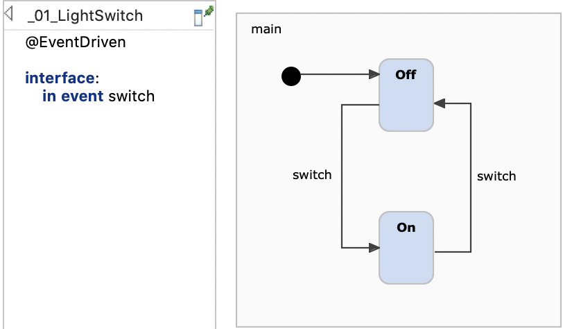
State machines as a whole can be active or inactive. If a state machine is inactive then no state is active and it won’t react on any event. If a state machine is active then is has at least one active state and it is ready to react on events. Entering a state machine activates it exiting deactivates it. If you enter the light switch state machine then Off is the first active state. The first active state is called initial state and is defined by the entry node whose single outgoing transition points to Off.
The statechart can be simulated in Itemis CREATE via right-click -> Run As -> Statechart Simulation.
The Second Iteration: Variables
While the classic theory of input/output automata is only aware of events, Harel statecharts and as such CREATE statecharts have many more features, including variables. Variables allow to use quantitative values in statecharts and are very comparable to variables in programming languages.
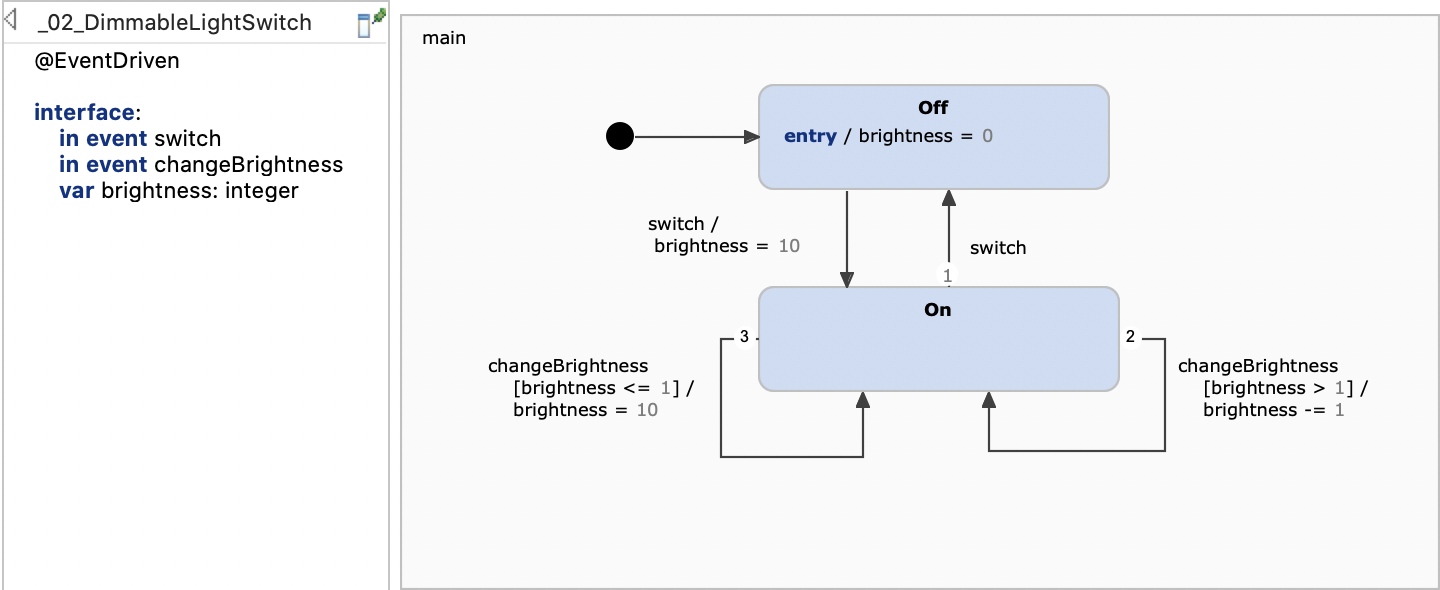
To explain the use of variables we extend the light switch by adding dimming functionality. The light switch supports ten different dimming levels. It still defines the states Off and On with mutual transitions which are triggered by switch events.
To handle the dimming functionality the light switch statechart defines two additional elements:
- The variable brightness holds the dimming level of the light. Changing this variable’s value corresponds to changing the lamp’s brightness.
- The additional event changeBrightness increases changes the dimming level incrementally.
To handle the brightness level correctly the statechart must maintain its value depending on the active state and the occurring events. As such it defines the following rules:
- Whenever
Off is active
brightness must be 0. This is enforced by the
Off state’s
entry action which is defined as
entry / brightness = 0. This action assigns 0 and is executed whenever state Off is entered. - When the light switches from Off to On then the brightness must be set to the maximum value of 10.
- If On is active and changeBrightness is requested and brightness is larger 1 then the brightness value is decremented. This rule is specified by an additional transition which reacts on the changeBrightness event and uses a guard condition which must become true for taking the transition. The proper variable assignment is specified as a transition action. The target of the transition is the state itself as the switch should remain in the On state. Such transitions are called self transition.
- If On is active and changeBrightness is requested and brightness equals 1 then the value is reset to 10. Here again an additional transition with guard and action is defined to cover the desired condition and effect.
This example shows how variables can be used in conjunction with more complex conditions. Variables can be assigned and can also be used in conditions and calculation expressions. Actions can be specified as part of a transition as well as part of states.
The Third Iteration: Composite States
Normally, a statechart does not only consist of two states. The specification of even simple systems require tens and more complex systems hundreds of states and transitions. To cope with large number of states the base concept of composite states can be used.
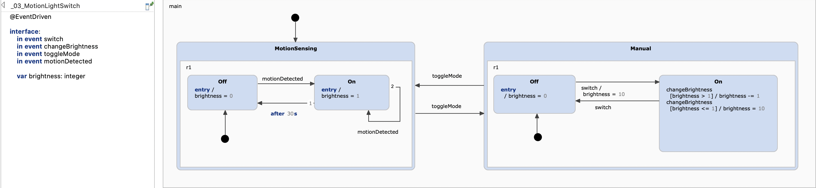
Let’s enhance our light switch to explain this in more detail. The light switch now provides an additional motion sensing mode which automatically switches the light on and off depending on the input of a motion sensor. Initially, the light is off, but whenever the motion sensor senses a motion, it turns the light on. After 30 seconds without any motion the light is turned off again. As manually switching and dimming the light should still be supported the existing statechart must be extended.
First, an additional event toggleMode is defined. This is used to toggle between the already existing manual and the automated motion sensing mode. To model these modes two additional states are introduced.
- The composite state Manual contains the existing behavior. These are the On and Off states of previous statechart. Here only the dimming transitions were replaced by local state reactions.
- The composite state
MotionSensing is completely new and contains the states
MotionSensing.On and
MotionSensing.Off. These handle the
motionDetected event. The required timeout is specified using the time trigger
after 30s. If the state does not change for 30 seconds then a time event is raised which will cause to switch the light off.
A composite state is a state that contains one or more other states (sub states). One of the advantages is the possibility to group states into logical compounds and thus make the statechart more comprehensible. Another advantage is the option to exit a composite state by transitions that have the composite state as their source states, not any substate. If such a transition is executed, the composite state is left regardless of which of its sub states are active at the moment. You could achieve the same without composite states, but it would be cumbersome since you would need a transition from each of the plain states in the group to the „outside”.
The transitions which toggles between MotionSensing and Manual state are defined for the composite states. This implies that the transitions will be taken independent of the concrete active sub state. So all sub states share the behavior of their parent states.
If you want to learn more about composite states, you can check out our Hierarchical tatecharts example or the chapter Composite states in our documentation.
The Fourth Iteration: History Entries and Named Interfaces
We already discussed the default entry behavior for regions and how sub states are activated. Histories provide an extension to this mechanism and this section clarifies how history entries work, what they do, and especially what they don’t do. To illustrate this, we introduce another mode to our light switch: light sensing. When operating in light sensing mode, the light control automatically turns on the light when it is dark and turns it off when it is bright. For this purpose a luminosity sensor is used. It permanently senses the ambient brightness and fires luminosity.bright or luminosity.dark events all the time. It is out of scope how „dark” and „bright” are defined and how they are configured in the luminosity sensor. Suffice to say that the sensor is always raising events – say, multiple times per second.
As before the light switch is either operated manually or operates automatically. When in automatic mode, the light switch functions either as a twilight switch as explained above or as the already introduced motion sense switch (see the previous iteration). The user interface gets another button to toggle between the two modes via the user.mode_button event. The light switch is starting to change into a full light control module.
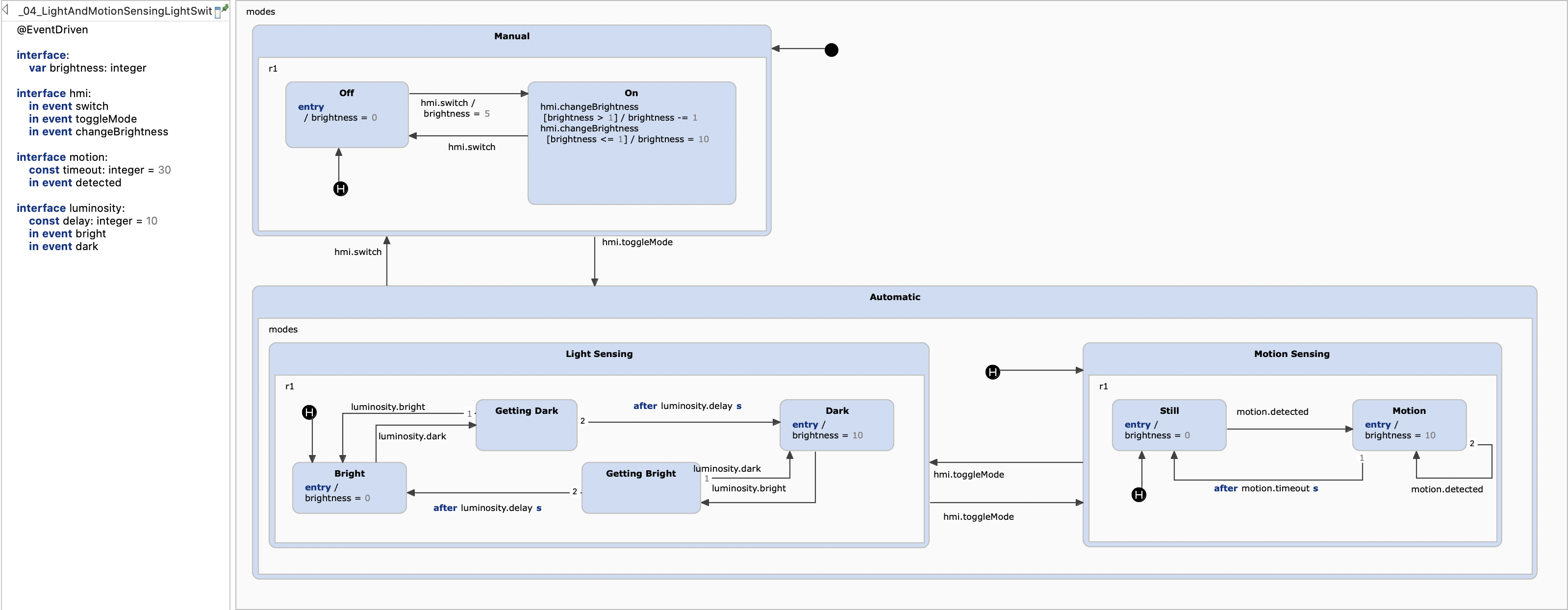
As we added a couple of additional declarations we now use named interfaces to group the different events and variables. This grouping makes the design more clear and provides a better overview. The usage is not different except for the fact that the interface name must be used when referencing its declarations.
The automatic modes are grouped into the Automatic composite state. That state is subdivided into a composite state for the twilight functionality and another one for motion sensing. We have discussed motion sensing before, but the Light Sensing composite state deserves some explanation. When the ambient brightness is changing from day to night or from night to day, the luminosity sensor doesn’t deliver consistent values. Rather small fluctuations are causing a succession of quickly alternating luminosity.dark and luminosity.bright events. Having each of these events turn the light on or off, respectively, would result in a flickering lamp for some time during twilight. To avoid this, the state machine requires a certain permanence in the luminosity sensor’s results before actually toggling the light’s state.
This is done like this: During the day the Light Sensing composite state’s Bright sub state is active. In this state the state machine listens for luminosity.dark events. These events are starting to be raised when it is about to get dark. First they come in spuriously, later there are more luminosity.dark than luminosity.bright events within a given period of time, until only luminosity.dark events are raised. The first luminosity.dark changes the state from Bright to Getting Dark. In this state we are waiting until a certain time has passed, e. g. 10 seconds, to be configured as constant luminosity.wait_time. However, each luminosity.bright event brings the state machine back to the Off. Only if the waiting time has passed without any lum_sensor.bright interfering, the Dark state is reached and the light is turned on. The analogous happens in the morning when the first light of the day is close. The twilight switch is also robust against short disruptions like overshadowing the sensor during the day or illuminating it briefly by a car’s headlamps during the night.
An important requirement is that any of the automatic modes can be interrupted at any time by manually operating the light switch via switch. When the user later raises a mode event, the state machine should return to that particular sub state somewhere down in the Automatic composite state that was active before the manual intervention. Similarly, when toggling between Light Sensing and Motion Sensing the state machine should remember the respective active sub state and return there when control is turned back.
That’s what history entries are good for. The statechart contains a couple of shallow history entries. A shallow history state, contained in a composite state with a set of sub states, remembers which of these sub states was active when that composite state was left.
The shallow history state in Automatic remembers whether Light Sensing or Motion_Sensing was active when Automatic was left, but it doesn’t remember which state was active within the active one of these two. On re-entry, the history state would activate either Twilight or MotionSensing, but these would use their respective entries. This is why there is a history state in each of them as well.
If you have worked with history states before, you might be inclined now to say: "A deep history state would have been the correct thing here." However, you would only be partially right. A deep history state remembers the active state in its own region and everything that was active inside of this state, recursively down to the lowest level. We might spare the two shallow history states in Light Sensing and Motion Sensing. But it would not behave in the same way – a history state is activated only when its containing region is actually left. Using one deep history state would not allow to remember the active state in MotionSensing when switching to Light Sensing, and vice versa. The deep history state would be activated only if we left the whole Automatic composite state – and when switching between automatic modes this won’t happen.
More information on history states can also be found in the History States example or the corresponding chapter in our documentation.
The Fifth Iteration: Orthogonal States, Internal Events and Operations
The different versions of light switches which we discussed so far define a couple of states but are quite simple in that respect that at any time at most one single state is active. You may object that hierarchy made up of composite states features a set of active states. This is not really true. Composite states just group a set of states but are not independent of their sub states. Leaf states are the real active states and the activation of a leaf state implies that also all its parent states are active. The leaf states also inherit the parent states behavior. There are scenarios which require orthogonal states (sometimes also called parallel states or and states).
Additionally, there are also scenarios where calculation become so complex that you don’t want to maintain them within a statechart. In these cases operations can be applied.
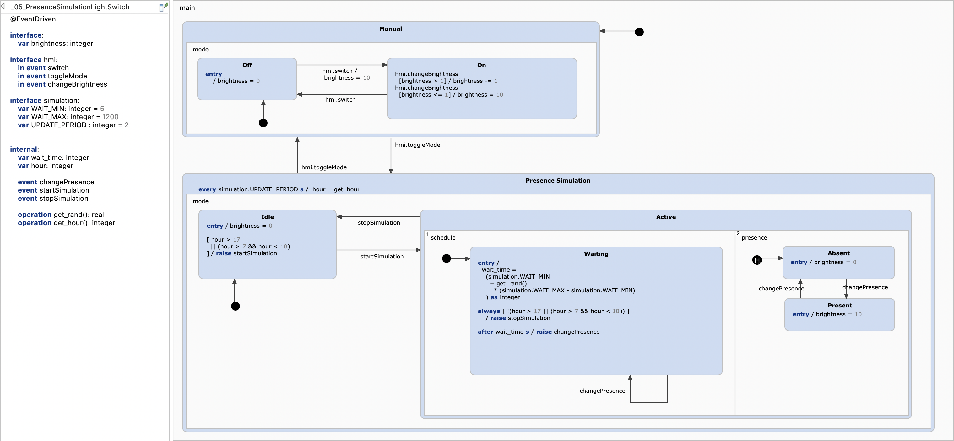
To illustrate these concepts we define a variant of the light switch which includes a presence simulation. It behaves as if a person operated the light at sensible and irregular intervals although nobody is present. The presence simulation is active on certain hours of the day only, namely from 17:00 to midnight and from 06:00 to 10:00. Here the motion detection and the twilight detection are left out for clarity.
To define the presence simulation the orthogonal state Active is defined. It contains two sub regions which are independent of each other and are executed virtually in parallel (their order is relevant, though). Each region can contain one active state. Each region is caring about different aspects. The region schedule includes a single state which cares about scheduling the next changePresence event. This event in turn is consumed by the presence region which switches the light on and off.
The events changePresence, startSimulation, and stopSimulation are internal events (also called local events) which are raised by the statechart itself when a certain condition is fulfilled. They can’t be raised by the environment and are not visible externally. These internal events will be processed directly after the current event. So interbnal events can be used to chain multiple processing steps. The states Idle and Waiting raise these internal events.
The definition of Presence Simulation get quite complex. There are especially a couple of textual rules and expressions which include calculations. Additionally, a modeler may require functions which are not directly available within the statechart. However, CREATE SCT allows you to implement your own operations to overcome these limitations. An operation is called from the state machine itself, so you don’t have to care about when and how they will be called. Operations can receive arguments from the state machine and return a value, exactly like a normal function or method call. Operations are declared by the statechart but are not defined within the statechart and must be implemented externally. The presence simulation uses two operations:
get_hourto ask for the current time of day to decide if the presence simulation must be activated.get_randto ask for a random float to calculate a random waiting interval in minutes between WAIT_MIN and WAIT_MAX.