Table of contents
Statechart elements Copy link to clipboard
Regions Copy link to clipboard
CREATE Statecharts are organized in regions. Hence it is possible to organize multiple state machines in different regions and to run them virtually concurrently.
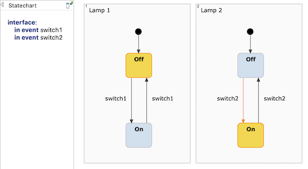
Orthogonal regions
Regions typically contain states and transitions. A state in turn can contain one or more regions, turning it into a composite state (contains one region) or an orthogonal state (contains two or more regions).
States Copy link to clipboard
States are the central elements of a state machine. A state has to be placed inside a region and must have a name that is unique within this region. During state machine execution, a state is either active or passive.
A state can have behavior. The behavior specifies which actions are executed on which conditions. Such actions can be triggered by entering the state, leaving the state, occurrence of events, conditions becoming true, or time passing. The behavior specification is a text in a state’s box and consists of a sequence of local reactions .
The state Countdown in the sample statechart below has three local reactions:
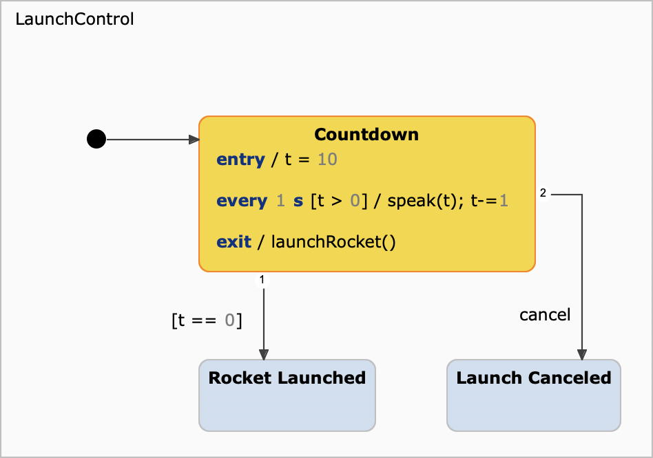
State example: A simple state machine to launch a rocket.
When the Countdown state is entered, it sets the counting variable t to 10. As long as that variable’s value is greater than 0, each second it gets counted down by 1. The operation speak provides audible information on how many seconds to go until the rocket is launched. If t has been counted down to 0 – checked by a transition’s guard condition –, the Countdown state will become inactive and launch the rocket upon exiting. The countdown can be aborted anytime before launch by a cancel event. (See figure "Transition example" for a different state machine which solves the same task but puts more emphasis on transitions.)
The state’s behavior contains a subtle error. Can you spot it?
Transitions Copy link to clipboard
A transition is the transfer of one state to another. A transition is diagrammed as an arrow leading from a source state to a target state. When a transition is taken, the source state ceases to be active, and the target state becomes active instead.
A transition should have a reaction . A transition’s reaction specifies
- what the conditions for this transition to be taken are, and
- which actions, if any, are to be executed when the transition is taken.
The occurrence of an event, a condition becoming true, or time passing can trigger a transition. The transition’s reaction is attached to the transition’s arrow as a text. Its syntax can be found in the section on reactions.
Please note: Transitions without a reaction are possible, but useless. They will never be taken.
Here’s an example:
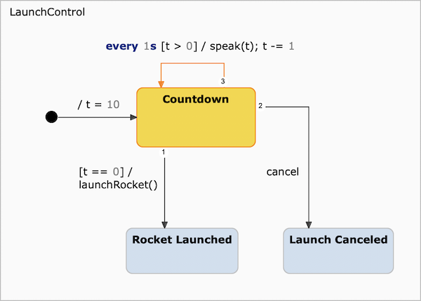
Transition example: A simple state machine to launch a rocket.
The initial transition’s effect sets the counting variable t to 10. As long as that variable’s value is greater than 0, every second it gets counted down by 1. The operation speak – executed as one of a transition’s actions – cares for audible information on how many seconds to go until the rocket is launched. If t has been counted down to 0 – checked by a transition’s guard condition –, the rocket is launched. The countdown can be aborted anytime before launch by a cancel event which triggers the appropriate transition to fire. (See figure "State example" for a different state machine which solves the same task, but puts more emphasis on states.)
Figure "Transition syntax overview" shows how the syntax of a transition reaction is defined.
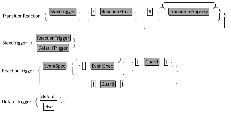
Transition syntax overview
Transition priorities Copy link to clipboard
If a state has several outgoing transitions, several of these transitions could in principle fire at the same time, dependent on the events that occured and on guard conditions.
Consider this example:
![Transition priorities [1] Transition priorities [1]](https://www.itemis.com/hubfs/solutions/itemis-create/documentation/images/sclang_elements_transitionpriorities.png)
Transition priorities [1]
Which transition will be taken if the state machine is in state A and event e1 occurs?
Fortunately, itemis CREATE state machines behave deterministically, so this question can be answered unambiguously. Outgoing transitions of a state have a definite order and are prioritized by that order. The state machine checks the transitions one by one in this order and executes the first transition that fulfills all prerequisites for firing.
As you can see in figure "Transition priorities [1]", little numbers at the transition arrows indicate their priorities. This numbering is shown only if the option Show transition priority in Window → Preferences → itemis CREATE → Diagram appearance has been activated. By default, this option is not activated.
The order of transitions is a property of their source state. In the example above, the transition priorities of state A appear like this in the properties view:
![Transition priorities [2] Transition priorities [2]](https://www.itemis.com/hubfs/solutions/itemis-create/documentation/images/sclang_elements_transitionpriorities_2.png)
Transition priorities [2]
To change priorities, select a transition in the properties view and click on the up or down button as appropriate.
Choices Copy link to clipboard
A
choice is a pseudo state. It is used to model a conditional path. If a choice’s incoming transition is taken, its outgoing transitions are immediately evaluated to decide which path to take. To ensure there is always a valid path, a default transition can be defined with the trigger
else or
default.
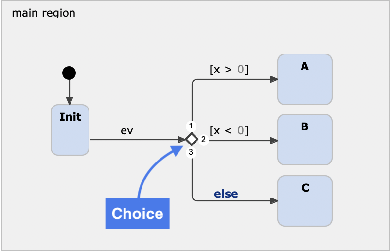
Example with a choice node and else-transition
Composite states Copy link to clipboard
itemis CREATE allows to express state hierarchies by the means of composite states and subdiagrams.
A composite state is a state that contains a region with further substates. It can be used to group states into logical compounds and thus make the statechart more comprehensible.
When a composite state is entered, its entry node denotes the substate to be activated. A composite state can specify multiple entry nodes with unique names. Incoming transitions of the composite state can specify the desired entry node to take for entering the composite state.
When a composite state is left, all active substates are also left. A composite state can specify multiple exit nodes with unique names. Outgoing transitions of the composite state can specify the relevant exit node for them.
See the sections on Entry and exit points for further information and examples.
Entry and exit points Copy link to clipboard
A standard UML composite state is always entered via its initial state. The latter denotes the inner state that is to be activated, unless a history state tells otherwise. Since there can be only a single initial state per region, a standard UML composite state always starts at the same inner state (history states aside).
Unlike UML composite states, however, composite states in CREATE Statecharts can additionally denote specific named entry points. A transition leading to a composite state can specify the entry point to be used instead of the initial state.
Analogously, a composite state can have named exit points. Outgoing transitions of that composite state may specify which exit point to react to, and thus lead to different target states, depending on which of the source composite state’s exit points has been taken. A blank transition with no trigger or guard reacts to all exit points, and is needed when a composite state contains a default exit point.
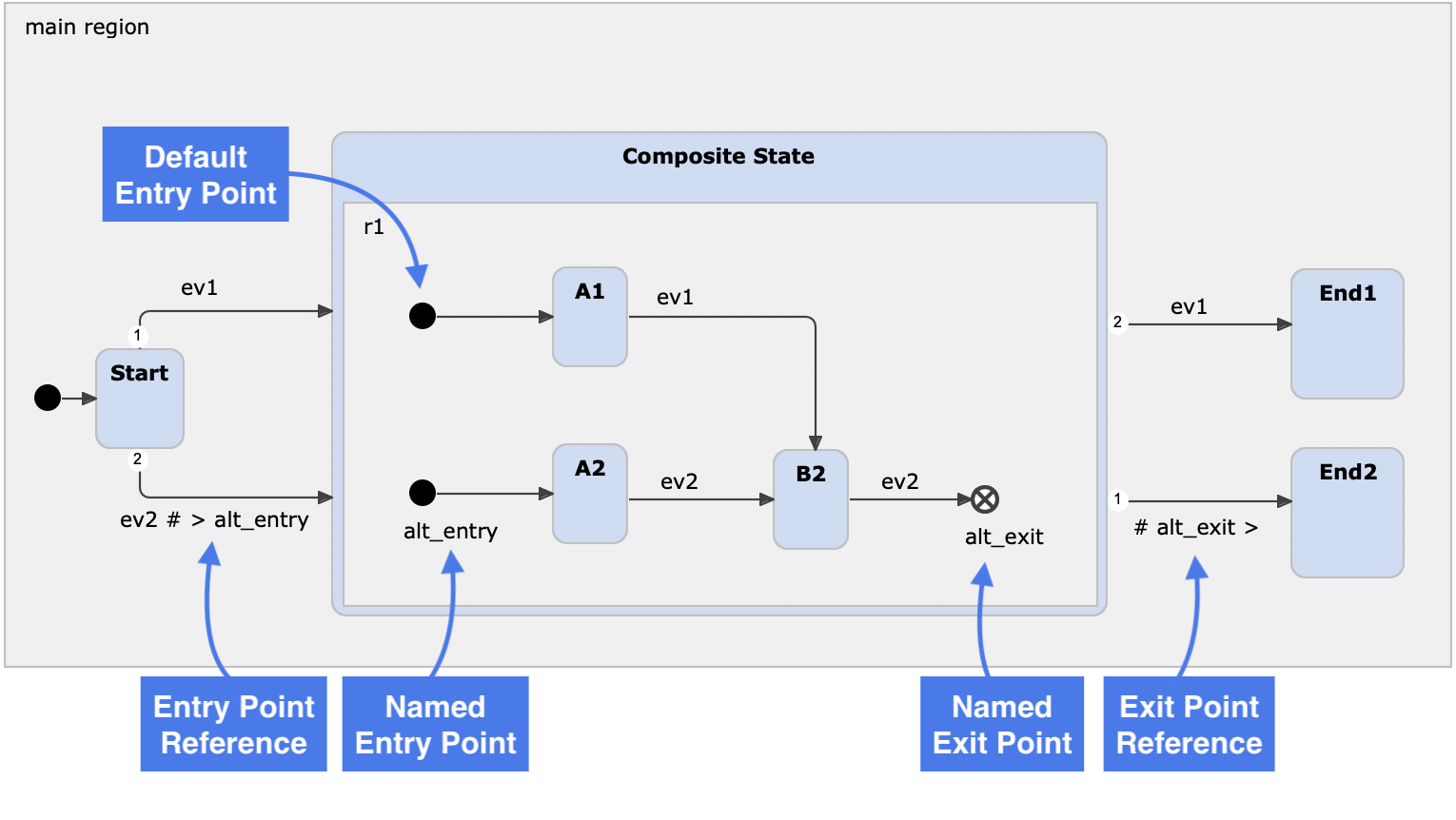
Entry and exit points overview
The syntax to connect a transition to an entry point with the name entry-point-1 of a target composite state is as follows:
# >entry-point-1
A named exit point can be used as follows:
# exit-point-1> [ exit-point-2> ]…
It is also possible to specify both entry and exit points in a single transition specification. The order of exit and entry points is irrelevant. Instead, the position of the
> character is decisive:
- If the
>character is to the right of a name, like inexit_name>, that name denotes an exit point. - If the
>character is to the left of a name, like in>entry_name, that name denotes an entry point.
The sample statechart in figure "Entry and exit points" contains two composite states:
- The composite state Process models a process with two passes (states) A and B. If both passes succeed, the composite state is left via the no_problem exit point. However, if an error occurs in either A or B, the execution flow proceeds to the problem exit point and leaves the composite state there.
- The composite state Handle result is intended to handle the processing result, be it success or failure. It has two entry points success and failure.
The question is how to connect the exit points of Process to the corresponding entry points of Handle result. This is done by two transitions leading from Process to Handle result and appropriate specifications.
The transition shown on the left specifies
# no_problem> >success. This means: If the source composite state is left via the
no_problem exit point, then enter the target composite state at the
success entry point. The specification of the transition on the right is analogous: If the source state is left via the
problem exit point, then enter the target state at the
failure entry point.
Alternatively,
Process could have been modeled with two different error exit points, say
error_1 and
error_2. This would allow to respond differently to different error conditions, while still enabling to catch them both with a single flow. A transition with
# >error_1 >error_2 problem> would do so.
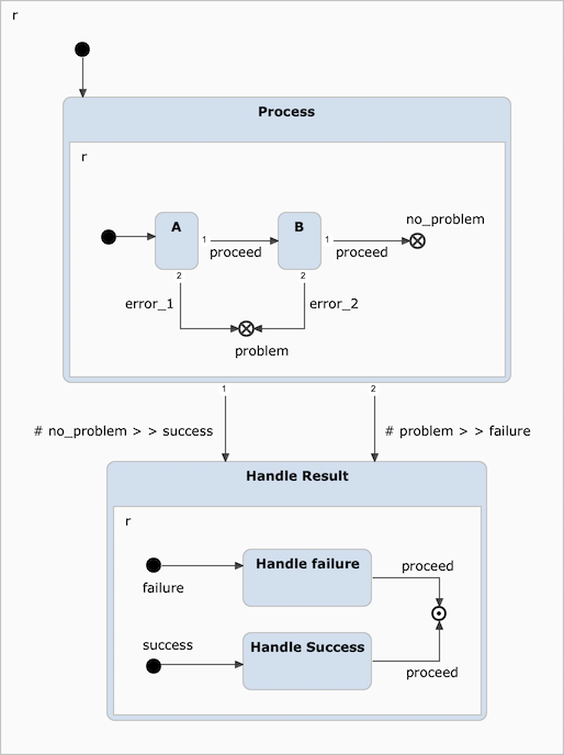
Entry and exit points by example
The entry or exit points to take have to be specified at the right-hand side of a transition specification. The corresponding syntax element is the TransitionProperties non-terminal symbol that is shown in figure "Transition syntax overview". It is part of the TransitionReaction.
More on entry and exit points can be found in sections "Entry points" and "Exit points".
Entry points Copy link to clipboard
When a state machine starts or when the control flow enters a region, an entry point, or simply entry, defines which state is to be activated first. The flow passes through the state machine’s or the region’s entry point and transitions to the target state the entry point’s transition is pointing to. This state becomes active.
An entry point has a single outgoing transition and no incoming ones. Its outgoing transition has neither a trigger nor a guard condition. It is always taken immediately.
An entry point is depicted as a filled circle, see figure "Entry and exit points overview".
Default entry point and initial state Copy link to clipboard
An entry point without a name is called the default entry point. It is similar to the UML’s initial state. However, while the transition from the initial state to an ordinary state may specify a guard, the transition sourced at an entry point cannot.
A region may have at most one default entry point.
Named entry points Copy link to clipboard
The default entry point specifies a single entry point into a region. A region can provide a multitude of additional or alternative entry points, thus implementing different kinds of behavior, depending on which entry point has been taken. If a region comprises multiple entry points, these entry points must have names. An entry point’s name must be unique within its region.
The default entry point implicitly has the name default. Alternatively, it is possible to explicitly give the name default to the default entry point. Semantically both variants are equivalent. Whether an entry point has no name or has the name default, in both cases this entry point is called the default entry point.
An incoming transition to a composite state can specify the named entry point it shall lead to. For details, see section "Entry and Exit points".
Named entry points have no equivalent in the UML.
Exit points Copy link to clipboard
An exit point, or simply exit, is a pseudo state that is used to leave and deactivate a composite state. Exit points are counterpart to entry point. See section "Final state" for a different way to terminate a region or state machine.
An exit point may have multiple incoming transitions and has no outgoing one.
An exit point is depicted as an unfilled circle with an X-shaped cross, see figure "Entry and exit points overview".
Within a region, multiple exit points are allowed. Each exit point must either have a name that is unique within its region or be the default exit point. The default exit point is either unnamed or has the name default, which is semantically equivalent. A region may have at most one default exit point. For details on how to connect named exit points to transitions, see section "Entry and exit points".
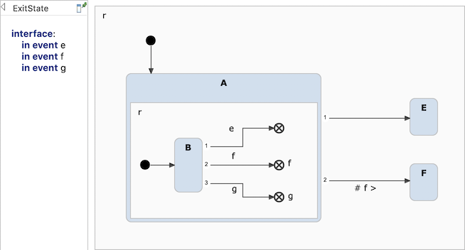
The event
e leads to the unnamed (default) exit point, which is connected to the blank transition. The event
g activates the transition to the exit point named
g, for which no specific transition exists, so the blank transition to state
E is taken. The event
f leads to the named exit
f. The lower outgoing transition is connected to this exit point via
# f > and takes precedence over the blank transition, thus state
F becomes active. Named exit points take precedence over the actual transition priority.
When the control flow of a composite state reaches an exit point in any of its regions, all states in other regions of that composite state, if any, are deactivated immediately. The composite state will be left and be deactivated. It maintains no status information that could be probed from the outside. In other words, reaching an exit point in one of a composite state’s regions has severe consequences for all the other regions, since they are exited and disposed immediately. After that, the containing composite state is also exited. There must be an unguarded transition that catches the exit and leads to another state outside of the composite state. The semantics of an exit point is different from that of a final state; please see section "Final state" for details.
Named exit points have no equivalent in the UML.
Final state Copy link to clipboard
A final state denotes the end of the execution flow of a state machine or region. See section "Exit point" for a different way to terminate a composite state.
A final state is depicted as an unfilled circle with a smaller filled black circle inside.
Like a regular state, A final state can have multiple incoming transitions.
Within a region, only a single final state is allowed, but each region may have its own final state.
When a region reaches its final state, control stops there and waits until all other orthogonal regions, if any, have reached their respective final states, too. The semantics of final states is different from that of exits; please see section "Exit point" for details.
Please note: In itemis CREATE, final states are proper states. This is different from the UML, where a final state is a pseudo state, i.e., in the UML a final state cannot have any properties that normal states can have, except for a name.
Orthogonal states Copy link to clipboard
An orthogonal state is basically a composite state with more than one region. These regions are executed virtually concurrently. Please note the word virtually! itemis CREATE does not guarantee in any way that orthogonal regions are really executed concurrently. At the moment, no code generator utilizes threads to achieve this. Orthogonal states should rather be understood as a manner to have two or more sub-statecharts working together, however, they are executed one after the other in every cycle, and in a defined order: top to bottom, left to right. The same applies to multiple regions in the statechart itself. Please consult section "Raising and processing an event" for further information on region priorities and their meanings for the statechart execution.
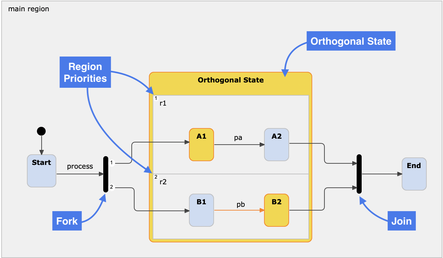
Orthogonal state and synchronization nodes
Synchronizations Copy link to clipboard
A synchronization is a means to either split a flow into several parallel regions of a substate or to join several parallel flows from orthogonal regions into a single flow.
The synchronization state corresponds to the UML’s concepts of fork and join. Whether a synchronization state behaves as a fork or as a join depends on its usage.
- A synchronization with a single incoming transition and several outgoing ones forks the flow into several regions of the same substate. These regions are executed in parallel, see section "Orthogonal states".
- A synchronization with several incoming transitions from parallel regions of the same substate and a single outgoing transition joins the incoming flows into a single flow of execution.
A synchronization state is shown as a thick horizontal or vertical line, as can be seen in figure "Orthogonal state and synchronization nodes".
For a synchronization to actually join the incoming transitions and execute the outgoing one, all of the following conditions must be met:
- All source states of all transitions leading to the synchronization must be active.
- All transitions leading to the synchronization must be active at the same run-to-completion cycle.
- All guard conditions that are specified in all these transitions must be fulfilled.
- If one or more triggers are defined, at least one trigger must fire at a point in time while the conditions above are met.
Figure "Orthogonal state and synchronization nodes" shows a sample statechart containing a forking and a joining synchronization. After having left the Start state, the synchronization state forks the execution flow into two regions r1 and r2. Both are part of the Orthogonal State and both are executed virtually concurrently. That is, when activating Orthogonal State, the substates A1 and B1 also become active. When the flows continues and both A2 and B2 have been reached, the synchronization state on the right-hand side joins the flows and transitions to substates End, making it the active state. However, as long as only one of A2 and B2 is active, the synchronization will wait for the other one to also become active, before proceeding to End. In case events and/or guards are used on the incoming transitions of a joining synchronization, all conditions need to be satisfied at the same run-to-completion cycle in order to join the flows.
Shallow history states Copy link to clipboard
A shallow history state is a pseudo state that is placed inside the region of a composite state. It is used to remember the last active state inside a composite state. This makes it possible to jump back to the remembered state instead of starting at the inner initial state again.
A history state saves the current state exactly when its containing region is left. A shallow history state saves the state of the current level only. If you need to save the status of multiple nested composite states, use a deep history state.
The following example, showing the answering of a questionaire, explains this:
![Shallow history [1] Shallow history [1]](https://www.itemis.com/hubfs/solutions/itemis-create/documentation/images/docu_shallow_history_init.png)
![Shallow history [2] Shallow history [2]](https://www.itemis.com/hubfs/solutions/itemis-create/documentation/images/docu_shallow_history_nextQuestion1.png)
![Shallow history [3] Shallow history [3]](https://www.itemis.com/hubfs/solutions/itemis-create/documentation/images/docu_shallow_history_nextQuestion2.png)
Inside the answeringQuestions composite state, it is always possible to send a pause event, which will return to the init state. At this point, the previous state, i.e., the last-answered question, is saved to the shallow history state.
![Shallow history [4] Shallow history [4]](https://www.itemis.com/hubfs/solutions/itemis-create/documentation/images/docu_shallow_history_pause.png)
When the continue event is triggered, the most recent active state inside of the composite state answeringQuestions is activated again. The respondent doesn’t have to answer the previous questions again, he can simply resume.
![Shallow history [5] Shallow history [5]](https://www.itemis.com/hubfs/solutions/itemis-create/documentation/images/docu_shallow_history_continue.png)
Deep history states Copy link to clipboard
A deep history state is similar to a shallow history state, but more complex. With a deep history state, the latest status of multiple nested states is remembered.
A history state saves the current state exactly when its containing region is left. A deep history state saves the status of multiple nested composite states. If saving the state of the current level only is sufficient, consider using a shallow history state instead.