Item Definition Copy link to clipboard
Modeling of the item encompasses functions, components, data, channels, and data flows. All elements can be put into the same system specification chunk. We recommend to use a unique chunk per entity type, though.
System Diagram Copy link to clipboard
You can also model the structure of the SUD graphically.
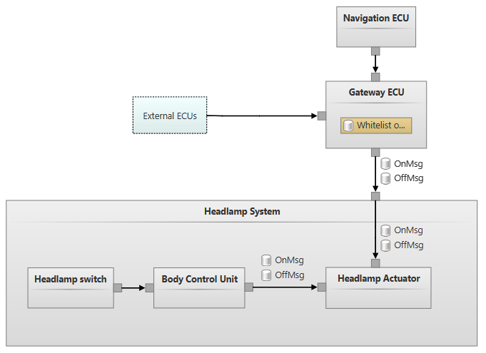
The system diagram editor is available via a specific chunk called System Diagram. The editor consists of a drawing pane with a white background on the left, a palette on the right, and a toolbar at the top. Above the toolbar, additional diagram options can be shown. The view inside the drawing pane can be panned by clicking and holding the right mouse button. The mouse wheel can be used to zoom the drawing pane.
![]()
New elements can be created using the diagram palette on the right. Click on an entry that you want to insert. Click another time at the desired location in the drawing pane to insert it. You can press and hold the
Ctrl key to keep the palette entry selected so that you can quickly insert several such elements at multiple places. Some palette entries, like data flows, require that you click multiple times in the drawing pane to complete creation.
An element’s name and title can be changed in the drawing pane with a double-click on the respective field.
Tip: Type a colon
: in the name or title field, to set name and title in a single step. Additional properties can be changed in the inspector.
Elements can be moved and resized. While dragging, all elements are aligned to an invisible grid.
Tip: Press and hold the
Shift key while dragging to disable snapping to the grid.
The routing of data flows can be changed by dragging the anchor points that are shown when a connection is selected.
Tip: Press and hold the
Alt key to delete existing anchor points.
From time to time, you might find it useful to use the Auto Layout checkbox in the toolbar, which will try to unclutter the drawing board. As a result, the modeled elements are grouped, and the data flows are routed automatically.
Note that you can always jump to the textual view. Press and hold the
Ctrl key while clicking on the system elements in the diagram to do so.
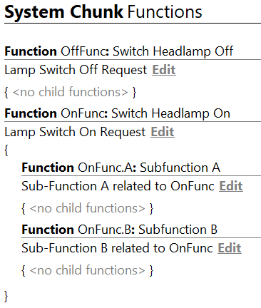
Functions Copy link to clipboard
When creating a new project, it already contains a chunk named Functions, where you can define the functionality of the item. Each function can be hierarchically divided into sub-functions.
Functions are created using the
Ctrl+Space key combination and are then further specified by the available attributes. Alternatively, other functions, sub-functions, or sibling functions can be created using the toolbar or the context actions on the right.
After creating some functions and sub-functions, the indentation will show you the level of each element. You can input a suitable description of a function in the element’s Inspector.
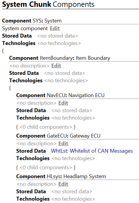
Components Copy link to clipboard
In a similar way as you have defined the functionality of the item, you can define its structure, based on Components, Data, Channels, and Data Flows. You can use the corresponding chunks in the Item Definition folder for that purpose. Please note that nothing hinders you to put all elements into one common chunk. You can also arrange elements following your own rules, like grouping elements by topic instead of by kind.
You can modify the following Component properties:
- Name: Short identifier of the Component, e.g. Cmp.1
- Title: Descriptive title of the Component, e.g. Navigation ECU
- Description: Description of the Component
- Stored Data: List of references to data that is stored on this Component
- Technologies: Reference to one or many technology tags, originating from the Catalog
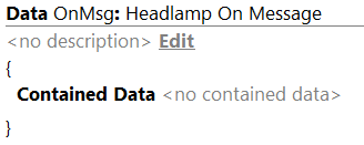
Data Copy link to clipboard
Data can be modeled as elements within the default Data chunk. Composition of Data is supported via the Contained Data property, where you can reference other Data elements. Furthermore, Data consists of a short name, title and an optional description.
Data is either stored as part of a Component or transferred as part of a Data Flow. This is modeled in the respective entity Component or Data Flow.
Channels and Data Flows Copy link to clipboard
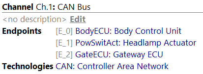
Channels and Data Flows can be modeled in the Channels chunk. A Channel represents a physical connection between two or many components. You can modify the following properties:
- Name: Short identifier of the channel, e.g. Ch.1
- Title: Descriptive title of the channel, e.g. CAN Bus
- Description: Description of the channel
- Endpoints: List of references to the components that are part of this channel.
- Technologies: Reference to one or many technology tags, originating from the catalog.
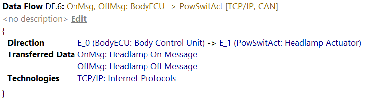
A Data Flow on the other hand defines a flow of information between exactly 2 components of a channel in a given direction. It refers to the endpoints of the channel which it is nested in. You can modify the following properties:
- Name: Short identifier of the Data Flow, e.g. DF.6
- Title: Descriptive title of the Data Flow, e.g. CAN Bus
- Description: Description of the Data Flow
- Direction: Defines the source and target of the Data Flow
- Transferred Data: List of references to data elements that are transferred as part of the Data Flow
- Technologies: Reference to one or many technology tags, originating from the Catalog. Can be derived from the Channel and extended by new Technology tags. E.g., if the channel defines CAN, the same technology applies to the nested Data Flows.
Function Assignment Copy link to clipboard
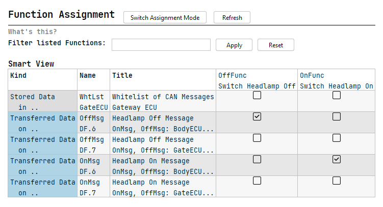
High-level functions need technical components, data and interfaces to be implemented in a system. To document this relationship, the function assignment chunk displays a matrix of all functions versus all modeled elements of the SUD. At first, no assignments are defined. You can use the checkboxes to assign elements to functions:
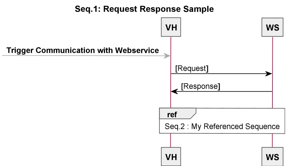
Sequences Copy link to clipboard
After having created the components of a system, in order to define channels and data flows efficiently, you can use sequences to describe the interactions of existing components. A sequence consists of multiple messages. itemis SECURE will create new channels, data flows and data for each described message. Using the
Ctrl+Space key combination on any data field in the message will help you finding the appropriate element.
Additional data elements can be created when selecting the data field and pressing
Ctrl+Enter. If the data is not present in the model yet, it can be created in the corresponding chunk. Keep focus on the message, then select the
create data action from the completion menu
Ctrl+Space.
If you have already modeled some data flows, you can easily re-use them in your sequences. To re-use a data flow, create a blank line in the sequence and start typing
via, press
Ctrl+Space, and select the data flow. This will create a new message between components and pre-select the data flow element.
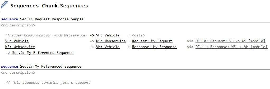
Message Types
The following message types can be used:
- Message between Components: Defines a data flow between two system components. Multiple data elements can be attached to the message.
- Triggered message: If one end of the message is not defined as a system component, the undefined end can be annotated with any textual representation that represents the trigger event.
- Sequence Reference: References another existing sequence within the sequences chunk.
- Comment: Allows commenting the sequence and adding further information that shall not be represented neither in the system model nor in the visualization.
- Blank line: Structures the sequence by introducing some space in the textual editor as well as in the graphical representation.
It is possible to convert any
message between components into any other message type and vice versa by selecting the message, pressing
Alt+Enter and selecting the appropriate transformation. Furthermore, you can invert the notation of your message, e.g. putting sender left or right of the arrow.
Data Flow Interactions
When adding a message between components to the sequence, itemis SECURE tries to map this message to an already existing dataflow. If no matching data flow is found, a new data flow is created on the fly.
During the system modeling process, the referenced Data Flow and the message might get out of sync. itemis SECURE detects and flags such inconsistencies and provides multiple options to resolve them. To resolve an issue, select the error and either press
Alt+Enter or click on the light bulb to the left hand side.
The following options are provided to resolve the conflict:
- Re-resolve data flow from message: This option tries to find a new matching data flow while keeping the existing data flow untouched. If no data flow is found, a new data flow is created.
- Update data flow from message: The linked data flow is updated with the information from the message. Use this option with caution since it alters the model! The data flow might already be used somewhere else.
- Update message from data flow: The message will be updated to match the linked data flow. Changes applied to the message will be overwritten.
Visualization
Sequences and messages are defined textually. A graphical visualization of sequences can be displayed next to them. To bring up the visualization, click the
"Visualize" button next to the sequence title, or right-click on the sequence and select
"Visualize sequence". Alternatively, position the cursor on the sequence, use the button in the toolbar, or press
Ctrl+Alt+V.